A diode thermometer with 1N4153, LM324
Saturday, October 31st, 2009My mom had long had problems finding a thermometer for measuring the temperature of the water when dyeing threads (with plants and mushrooms). The required temperature range is up to 100°C and I thought i surely could make a simple thermometer circuit for doing that.
First I was thinking of using an ATTINY25, as it has a built-in thermometer, but i quickly abandoned the idea. Now i had the idea to make it completely analog, using a diode, probably because I earlier had problems with diodes changing their forward voltages in varying temperature. Also, I thought I’d need a simple circuit to feed an analog panel meter.
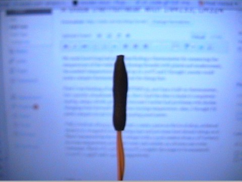
Well, I took an 1N4153, which cost 2 cents a piece in the local shop, soldered wires to it, wrapped it in insulating tape and put some heat shrink tubing on it. Then I measured the forward voltage (with a 330k resistor from a 9V battery) in room temperature, in boiled water and outside, in a frozen rain water container. That’s 0°C, 23°C and 100°C, roughly the range to be measured. 0.296V, 0.455V and 0.510V, respectively.

The 1N4153 Temperature Probe
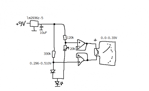
Well, that’s, unsurprisingly, roughly linear, so we could easily use it with an MCU, too, or easily calculate a threshold value for an overtemperature sensing circuit or something like that, but that’s not what we’re doing this time. We need a circuit, wich will convert the 0.296…0.510V of the diode to the 0.00…0.33V of the analog meter. Also, it needs to be inverted to get the values to increase when going from left to right on the meter. On my favorite electronics channel on IRC, we ended up with this design:

The schematic of the diode thermometer
The operational amplifier is an LM324 (of which i ordered a lot of 50 pieces or so some time ago, from ebay, very cheaply… plenty of them to use!), and, additionally to the schematic, it’s operating voltage is supplied from the 5V output of the regulator. The LED at the bottom of the drawing is to bias the voltages a bit, because LM324 isn’t able to sink enough current at the low voltages used otherwise.
Calibrating it was quite trivial: Take three measurements and utilize the regression feature of a pocket calculator, to make something like f(x) = Ax^2 + Bx, x being the temperature and f(x) being the position of the meter. It’s precise enough for this usage, at least.
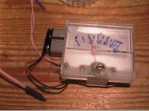
Here’s the completed thing:

The diode thermometer

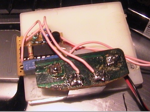
The back side of the diode thermometer
