Mirrored as part of a study of Minetest events of 2010 to 2019 and people involved, and in connection with a related book, events in 2017 to 2018, in particular, conferring upon host legal rights related to Fair Use.

A fix for the Co/Tech MultiTool tool holder

November 10th, 2009 by celeron55

I now got a replacement Co/Tech MultiTool (a cheap dremel-like thing) for free for the one that I broke some time ago. I found out that the build quality is a bit worse. It vibrates more, and the tool holder holds tools a bit tilted. I can’t do much for the vibration, but the tool holder was a real issue for me, as I’m going to try to mill PCBs with it, with tools smaller in diameter than the amount of how much it tilted the tool.

The problem was in the part that you turn to tighten the collet. It had the hole in the end significantly misaligned. Well, not any more. It seemed that the hole in the tool holder could be enlargened enough to make the hole well aligned in relation to the turning axis. And I happen to have an another dremel copy too, so…

I secured the tools head-to-head on a table (which was easy with the adapters I have made for attaching them to the router) and used a few mm’s thick grinding tool in the other one, and rotated the spindle of the other one manually.

And after 10 minutes of rotating it little by little, the tool holder works well:

istukankorjaus

istukankorjaus3

istukankorjaus4

A diode thermometer with 1N4153, LM324

October 31st, 2009 by celeron55

My mom had long had problems finding a thermometer for measuring the temperature of the water when dyeing threads (with plants and mushrooms). The required temperature range is up to 100°C and I thought i surely could make a simple thermometer circuit for doing that.

First I was thinking of using an ATTINY25, as it has a built-in thermometer, but i quickly abandoned the idea. Now i had the idea to make it completely analog, using a diode, probably because I earlier had problems with diodes changing their forward voltages in varying temperature. Also, I thought I’d need a simple circuit to feed an analog panel meter.

Well, I took an 1N4153, which cost 2 cents a piece in the local shop, soldered wires to it, wrapped it in insulating tape and put some heat shrink tubing on it. Then I measured the forward voltage (with a 330k resistor from a 9V battery) in room temperature, in boiled water and outside, in a frozen rain water container. That’s 0°C, 23°C and 100°C, roughly the range to be measured. 0.296V, 0.455V and 0.510V, respectively.
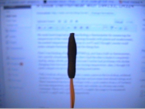
The 1N4153 Temperature Probe

The 1N4153 Temperature Probe

Well, that’s, unsurprisingly, roughly linear, so we could easily use it with an MCU, too, or easily calculate a threshold value for an overtemperature sensing circuit or something like that, but that’s not what we’re doing this time. We need a circuit, wich will convert the 0.296…0.510V of the diode to the 0.00…0.33V of the analog meter. Also, it needs to be inverted to get the values to increase when going from left to right on the meter. On my favorite electronics channel on IRC, we ended up with this design:
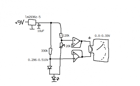
The schematic of the diode thermometer

The schematic of the diode thermometer

The operational amplifier is an LM324 (of which i ordered a lot of 50 pieces or so some time ago, from ebay, very cheaply… plenty of them to use!), and, additionally to the schematic, it’s operating voltage is supplied from the 5V output of the regulator. The LED at the bottom of the drawing is to bias the voltages a bit, because LM324 isn’t able to sink enough current at the low voltages used otherwise.

Calibrating it was quite trivial: Take three measurements and utilize the regression feature of a pocket calculator, to make something like f(x) = Ax^2 + Bx, x being the temperature and f(x) being the position of the meter. It’s precise enough for this usage, at least.

Here’s the completed thing:
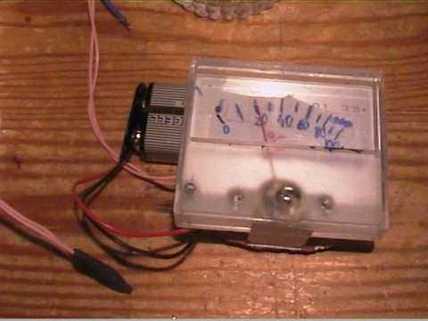
The diode thermometer
The diode thermometer

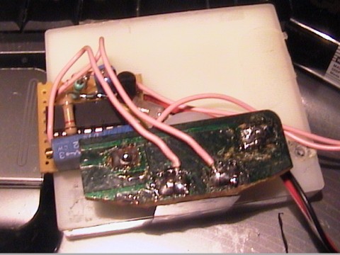
The back side of the diode thermometer

The back side of the diode thermometer

I made a line following robot!

October 29th, 2009 by celeron55

And it works very nicely. Here it is:

The line following robot

The line following robot


The robot in action

The robot in action

It uses a circuit like this (which i thought up and improvised myself):

The schematic of the line following robot

The schematic of the line following robot

The circuit uses a LM324 op-amp. The setup trimmer is a 10k one, with a 100 ohm resistor in series. When supplied from a 3.6V battery, The series resistor for the leds can be, for example, 100 ohms. The resistors in parallel to the photodiodes are 330k. The final transistors can be anything capable of handling the current. This time, BD681 was used. The IR LEDs and the photodiodes were disassembled from an old mouse.

The leds, photodiodes and the operational amplifier (LM324) were just glued to the cardboard, the power transistors soldered to the servo motors and then everything was soldered to them. The robot uses a tiny 50mAh 1S LiPo.

October 14th, 2009 by celeron55

I’ve been doing some other things instead of the CNC thing  for a few days now. The CNC router/mill/whatever (what’s the difference?) is having some kind of an identity crisis atm, because i don’t really know what i’m going to do with it.

I think i need to know it before i buy something new for the spindle. Surely it’s useless for a lot of things, but maybe I’ll find something to do with it. Probably milling PCB’s, if it proves out to be useful in that… which means i’ll just need to go and buy another mini drill for 20 euros.

Anyway, I built a ramp using scrap wood for my brother’s RC car:

size comparison

size comparison

It was meant to be “big enough” height-wise, and it sure is. It’s a bit too narrow, which of course isn’t a big problem if you are a good driver!

rc car jumping

rc car jumping

aut_3889

I have also been playing Command & Conquer Red Alert. Yes, the first one; the one which came out after the original C & C. Those two are probably the best video games I know of. Very original, runs on any computer, really good soundtrack. And very 8). 8) is the meaning of life.

Red Alert Screenshot (taken with a camera because print screen only gave out a mostly black screen)

Red Alert Screenshot (taken with a camera because print screen only gave out a mostly black screen. Yes, the screen is a bit broken but it doesn't disturb me too much)

Also, Windows 2000 is the best windows ever to be known. I installed it on the laptop i played Red Alert on and it just worked. (Well, you have to know where to get the drivers from and that you can enable the win95 compatibility mode with some strange command (which I always have to google))

HP still has their drivers for Omnibook XE3 available on their support site, which is wonderful.

How to Kill a Mini Drill

October 9th, 2009 by celeron55

I just broke my mini drill today which i used in the CNC mill. I guess I overloaded it when I cut some wood manually with it. It somehow burned and shorted some of the coils. Now the brushes make lots of long sparks and the drill has a fraction of the power it had before.

How to kill a mini drill

How to kill a mini drill

Some coils burned

Some coils burned

co-tech mini drill

co-tech mini drill