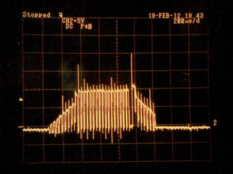
dcdrive2 phase voltage in oscilloscope
dcdrive2 is a BLDC(sensored/sensorless)/universal motor speed controller I made about two years ago. Mostly for fun, experience and for the possible uses in combat robots.
Here’s a random photo of dcdrive2 turning a BLDC motor at full speed I took today. It is a sensorless R/C car type motor. The waveform looks pretty much exactly like what a properly working BLDC controller should produce.
The strict limits of this design is about 10 to 45V of operating voltage (depending on regulator, FET driver and capacitor configuration), and it can supply at least 45 amps (haven’t really been able to test more, after some recent modifications).
Here’s a schematic of a version of it, for those interested.
Basically there is an AT90PWM3B (an easily programmable AVR (just like any atmega, but with a capable 3-phase bridge PWM controller)), a 3-phase MOSFET driver (IR2136x family) and the MOSFETs (I’ve been using IRF1405N).
The initial prototype used two DIY PCBs, the other being the high-current board and the other one containing the logic. Here is a shot of a testing setup on an RC car, including 22.2V worth of batteries:
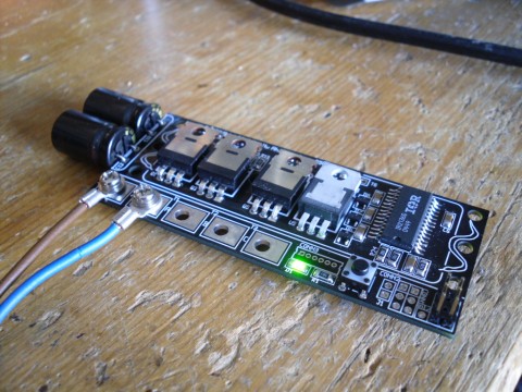
The final version uses a robust 4-layer PCB with thick copper layers and as good withstanding of high switching current as I could possibly come up with. I have a few boards laying around and could order more fairly cheaply, if somebody is interested.
I haven’t been able to accomplish proper load testing for it, because I don’t own large enough motors or vehicles or test benches that could stress it to the extent it should be able to withstand, but as for what I have been able to do, the power parts of it don’t seem to even know what failing means. 8)
Normally it is controlled using an RC servo PWM signal. I have also used it as the sole controller in a “melty brain” style fighting robot. This is pretty lightweight usage of it:
Also it is used for controlling the power in this one. Albeit not being brushless, this uses much of the voltage and current capacity of it. I think this was with a 45A current limit.


March 3rd, 2012 at 12:28
nice job looks pretty awesome,second test runs xd
March 20th, 2012 at 06:48
click here…
[...]electronics, etc.» Blog Archive » dcdrive2 phase voltage in oscilloscope[...]…